
- Links Page
- Image Gallery
- Resistor Calc
- HomeBuilt IRDA module
- Remote Control IR
- Remote Control DIYUHF
- Remote Control DIYUHF V3
- Remote Control DIYUHF Plantraco compatible
- Battle Circuit for Heng Long Tanks
- DSO Nano review
- Power Meter Monitor
© <in der past>
First things first, you'll need an IRDA module, I used a HP(Agilent)
HSDL-3610. The biggest problem I had with these is that they are SMT mount
components, and require a fairly steady hand at soldering to get the
little buggers on a PCB.
These are supposedly drop in replacements for
HSDL1001s, so one of those should work fine, but I believe a few extra
components may be required.
The spec sheet for the HSDL-3610 can
be found at
HP's web site.
The HSDL-3610 is only capable of SIR, which is only 9.6 - 115.2 kb/s. HP
also offers more powerful IRDA modules capable of 4 Megabit/s transfer
rate.
I ordered mine from Newark, they do a
reasonable small purchase online ordering.
The components required for the rest of the circuit are a 15 ohm resistor, a 0.47 microFarad cermaic capacitor, and a 6.8 microFarad electrolytic capacitor. Note that HP recommends that the cermaic cap be at most 7mm from the module, and I used a 10 microF electrolytic instead of the 6.8 microFarad tantalum they recommend (Radio Shack didn't have any). As usual, YMMV.
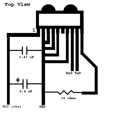
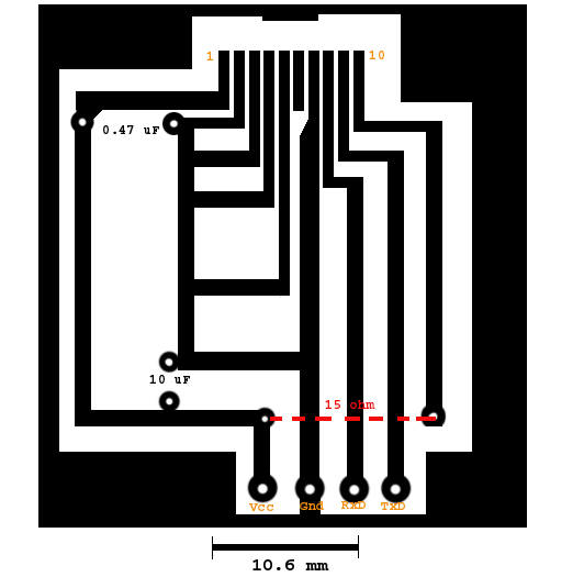
Soldering the components on is fairly straigtforward, except for the actual module, because it's meant for SMT. I tinned the points where the module was going to sit and the leads on the module itself, held it in place and gently applied a fine soldering iron to the copper traces, and waited till the heat liquified both blobs of solder. Not exactly pretty, but it worked.
Hooking it up to the IRDA header on my motherboard was simple, I glued two cd-rom cable plugs side by side to make a five-pin connector, and wired the appropriate wires to the leads off the PCB. I tested mine on both my BH6 and BP6 motherboard, and it should work on any standard motherboard with a 5 pin IRDA connector. (It might even work on the larger connectors, but you'll have to find the correct pins yourself).
5 PIN IDC MALE at the motherboard.
| Pin | Name | Description |
|---|---|---|
| 1 | +5v | Power |
| 2 | n/c | Not connected |
| 3 | IRRX | IR Module data received |
| 4 | GND | System GND |
| 5 | IRTX | IR Module data transmit |
I do suggest you mount the module in some sort of a shielded box with a small window, as I found that light interferes with operation, and I suspect that EMF would also have an effect (especially if you don't use shielded cable to your IRDA header.
Set your bios appropriately, which should be something like enabling IRDA on COM2 (which disables the actual COM2 port), and setting the transmit levels. I think I had to use HI for one and LO for the other, but this may vary with motherboards. Experiment and see what happens.
As expected, I take no responsibility if you fry your motherboard.