- Links Page
- Image Gallery
- Resistor Calc
- HomeBuilt IRDA module
- Remote Control IR
- Remote Control DIYUHF
- Remote Control DIYUHF V3
- Remote Control DIYUHF Plantraco compatible
- Battle Circuit for Heng Long Tanks
- DSO Nano review
- Power Meter Monitor
© <in der past>
DIY-UHF system
*BETA* This is a pretty basic beta version...with limited instructions included...consider yourself warned.
This system, in conjunction with an existing RC transmitter with four or more channels, forms a complete micro UHF radio system. There are two parts:
- The TX module taps into the PPM signal from the RC transmitter, and decodes the first four channels. The four channels are converted into a digital signal with a parity check bit, and then transmitted over a 900mhz frequency.
- The RX module receives the digitally encoded channels, and uses the values to drive 2-3 actuators plus a motor ESC.
Complexity wise, it's somewhat more difficult than the DIY-IR systems, but not too much of a progression.
Prototype pics
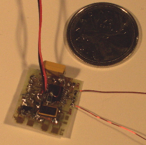

RX3 prototype
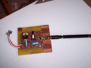
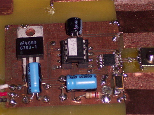
TX prototype
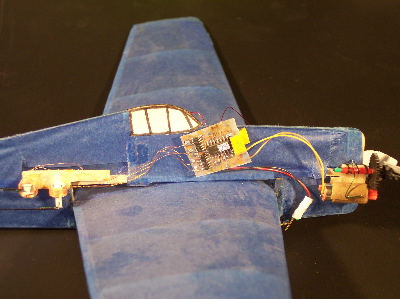
RX4 prototype on 12" hellcat
Stats:
- Currently hard-coded to 1 channel (915.00 Mhz), +90khz freq dev
- 9600 bps data rate
- 7-bit channel width (128 values) + 1 parity bit [dead-banding at center and extremes reduces this at RX side]
- 4 channels parsed on TX
- 3-4 channels produced on RX (AET, AETR)
- Single cell Lipo power (should be good for up to 5v)
- Throttle cut around 3/3.1 V on RX4 code (not tested)
- Prototype 4 ch RX weigh in around 0.85 g. Using a TSSOP for the PIC will probably further reduce weight.
- PFM performed on actuators (this code really sucks...hope to improve/replace it soon)
Notes:
- Tested on Hitec Flash 5 (so far)
- Tested with Logic low PPM signal (logic high setting possible, not tested yet)
- Tested with Hitec/Futaba channel ordering (JR & Sanwa settings possible, not tested yet)
- Range tested to a basketball court (so far)
- The TSSOP TX & RX chips are the hardest to solder, start there, and check for shorts between pins before proceeding
- Low battery LED on RX3 not tested.
- Pin assignments on PIC change from RX3 to RX4...don't mix up the PCBs and PIC code
- Make sure you bridge the jumper points on the RX board after programming the PIC, there's four (Vcc, GP0,GP1, MCLR). I just use a little solder so I can ICSP the PIC with updated code.
- My RF skills are limited, so I haven't really optimized it for range/signal rejection...feel free to contribute
- No schematic per-se, I was more concerned with routing on the RX and too lazy to copy my paper sketches.
- The PCB routing sucks...I know. But it works.
- There's some surplus code that I haven't found time to cleanup, including some interrupt code that isn't used
Downloads
Big thanks to Zlatko & RCGroups DIY-Electronics members
I can be reached at darkith /at/ gmail /dot/ com, or as darkith on RCgroups.
Commerical/for-profit use forbidden without permission.