- Links Page
- Image Gallery
- Resistor Calc
- HomeBuilt IRDA module
- Remote Control IR
- Remote Control DIYUHF
- Remote Control DIYUHF V3
- Remote Control DIYUHF Plantraco compatible
- Battle Circuit for Heng Long Tanks
- DSO Nano review
- Power Meter Monitor
© <in der past>
These are the assembly instructions for version 1.
They assume the user has a passing familiarity with soldering electronics and identifying components (resistors, capacitors, etc)
You may wish to perform steps 6 & 9 in advance. If you're planning on connecting the DBU with wire instead of a plug (see step 2) consider connecting the wires for step 10 in advanced (use color coded wires).
-
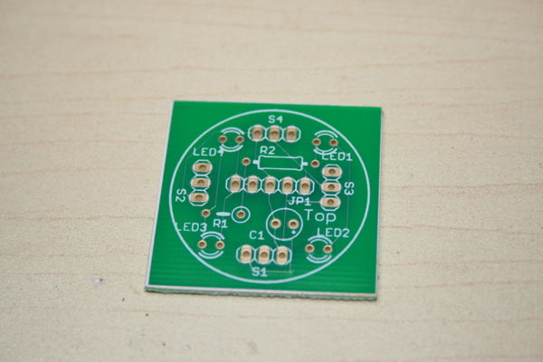
Find the DBU Printed Circuit Board (PCB). The top surface has the white silkscreening and is labelled "TOP". All components are soldered to the top unless noted otherwise. -
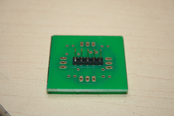
If you intend to use a removable DBU (mating connector not included) Solder the 1x5 set of pins to the bottom of the board at location "JP1"
A matching connector can be made by cutting an older floppy or IDE cable (not included), and soldering connectors to the pins (see below). -
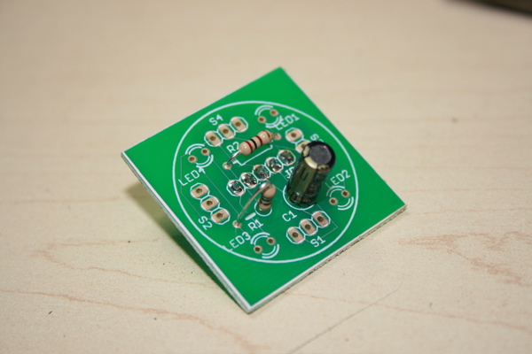
Solder two 100 ohm (brown, black, brown, gold) resistors at locations R1 and R2. Solder the 68 uF capacitor at location C1, being careful to match the polarity (the stripe is negative). -
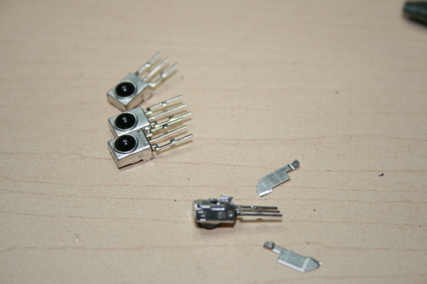
Carefully trim off the 2 "wings" from the 4 IR sensors. Avoid touching the pin to prevent damaging the components with static. -
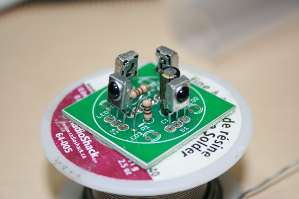
Solder the four sensors the board at locations S1-S4. The sensor domes must point outwards.
TIP: Solder them on the very ends of the leads, this will raise them up higher and ensure a less obstructed signal when battling -
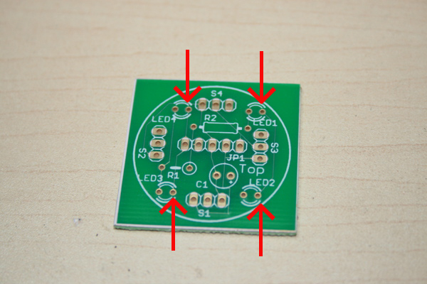
Due to an error in silkscreening, on early boards the LED polarity is obscured. Carefully orient the board as shown, and then mark the four holes with the arrows. These are the locations for the long leg of the LEDs.
Another way to orient them is to remember than when holding the board so that you can read the text "TOP", the long legs go in the right hand holes.
This has been fixed on newer boards, and the holes are marked with a "+" symbol. -
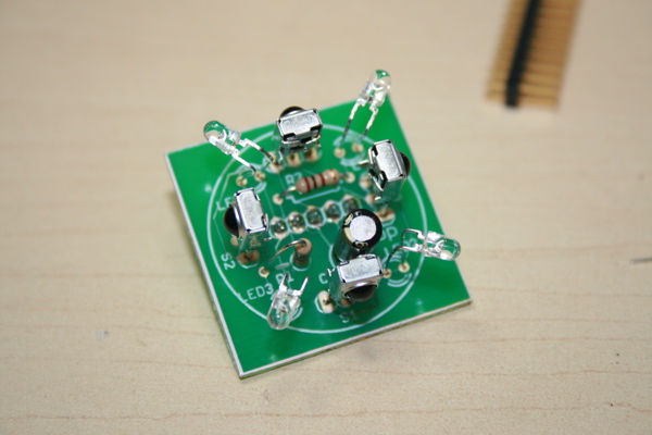
Then install the LEDs, with the long legs in the marked holes. You may want to carefully bend them so they are more visible from all directions.
TIP: Install them lower than the IR sensors (not as shown), so that you can place baffles around the sensors without obstructing the LEDS. -
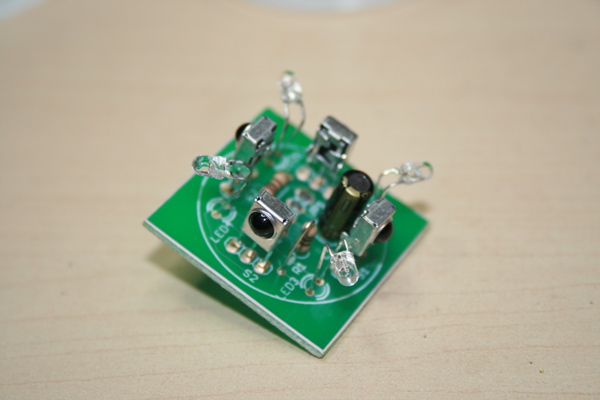
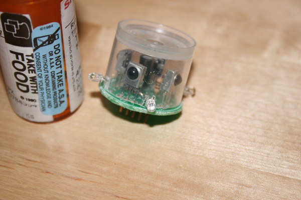
Completed DBU. -
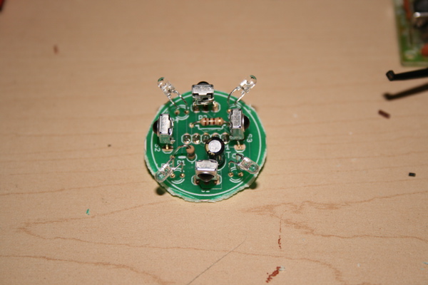
If desired, carefully trim the edges of the board back to the edge of the silkscreened circle. A pair of small diagonal cutters works if done carefully. Avoid damaging any of the components or cutting through any of the PCB traces on either side. -
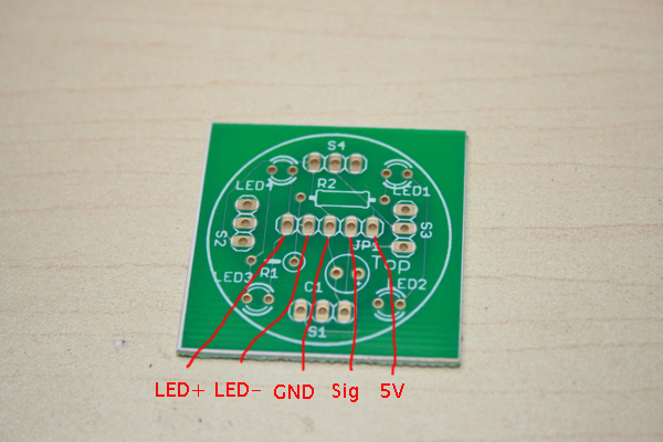
Unfortunately, there isn't enough room to label the pinout of the DBU on the board. Carefully use this diagram to connect the DBU to a DBC unit. If the connections are made incorrectly, you may damage your DBC & DBU.
Holding the board so that you can read the text normally and the label "JP1" is to the right, the pins are:
Starting at the left-most pin:
- LED+
- LED-
- GND
- Sig
- 5V (last pin next to JP1 text)
- Connect the IR LED as per the instructions for the DBC.
- Connect the DBU to the DBC. You should now be able to send and receive battle hits. Additionally, remote configuration changes will turn the "hit" LEDs on for a second.
-
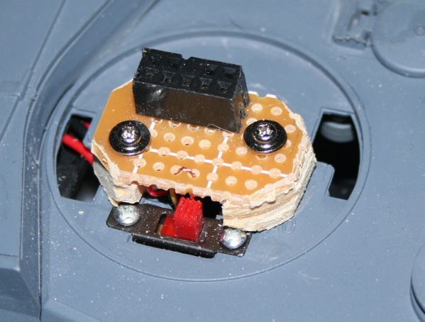
Tip: When I connected up my TBU/DBU, I pulled apart an old computer floppy drive connector. I removed the clip from the back and pulled the cable free, then cut it to the right width and pulled out all by 1 row of 5 pins. I soldered the pins to a scrap of PCB, they were *just* long enough. It works quite well, as the second row of pins prevent you from plugging in a TBU backwards (and you could probably key the DBU similarly by gluing a strip of plastic/wood to the bottom). -
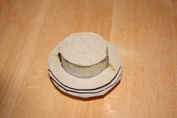
Quick and dirty cardboard filter. Works, but not exactly pretty. With a little care it might be possible cut a cleaner one and paint it nicely, but it would be prone to bends. -
Building an IR filter for the DBU
Find a suitable tube. I cut the bottom off a pill bottle (about 1" in diameter). Check if it passes IR light by placing it over DBU and seeing if it has a negative effect on the range at which the tank can be hit. If it doesn't pass IR light, you'll have to drill holes. If it does pass IR light, you can use windows or drill holes.
Then cut notches so that the hit LEDs can sit outside the tube (this prevents IR from leaking in the tube and drowning out the sensors). 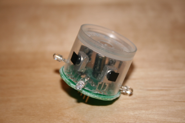
You can either mask out the sensors, or drill holes for the sensors. In this case, I masked the sensors out. Either way, you want to do this before painting.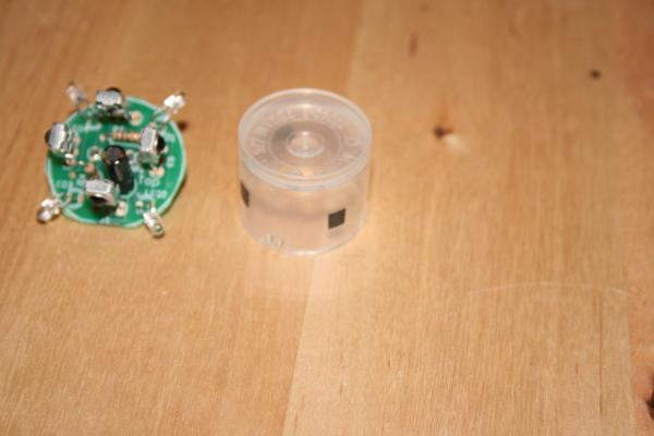
Tube with masked windows for sensors. I used electrical tape, a little under 1/4" square. Too big, and the sensors will take hits from angles too easily. Too small, well, that's not cricket!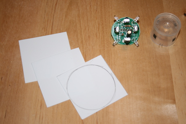
Take some styrene sheet and mark a 1.5"-1.75" circle on one. I used 3 fins, but more is probably better to limit ambient IR light. The goal is to limit the sensors to IR light that's coming from a horizontal direction.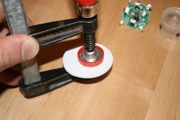
You can either sandwich the sheets between some cardboard or wood and cut them out with a hole-saw, or clamp them and cut them with a sharp pair of scissors and then sand them to a round shape.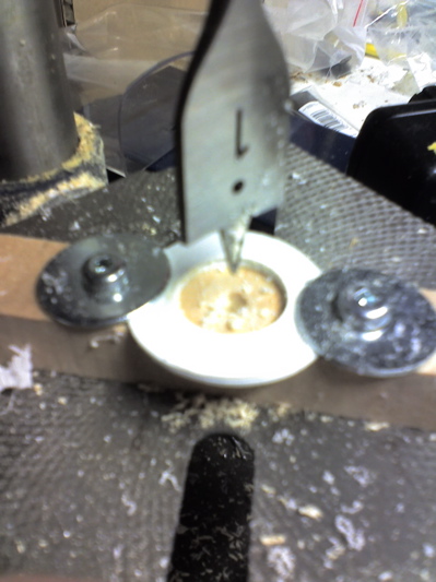
Then, either clamp the circles to drill press and drill a suitable size hole (1" in my case), or carefully trace a circle and then cut it out with a sharp x-acto knife. Carefully trim the hole to be just slightly larger than the tube (you need enough space for paint or you'll scrape it off the tube).
Apologies for the poor pic, didn't want to take the wife's nice digital SLR into my dank, grimy, greasy basement for fear of my life. ;)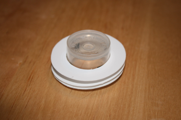
Test fit.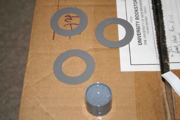
Paint. Use the right paint for the type of plastic the tube is made out of. I initially used the wrong paint and hand to repaint the tube (that's why the fins and tube don't match well, I'll repaint when I get a chance).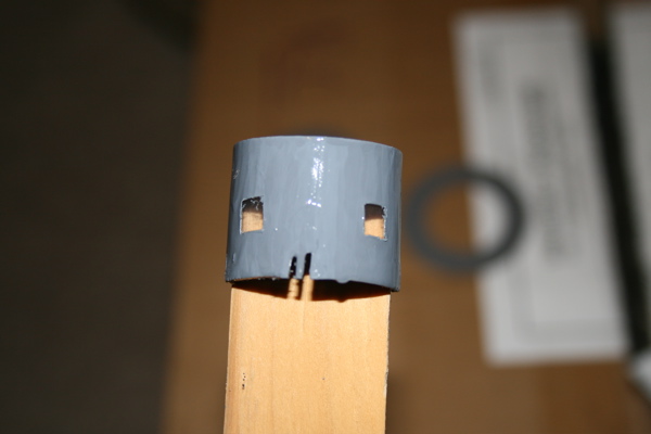
Carefully remove the mask if you decided not to drill holes.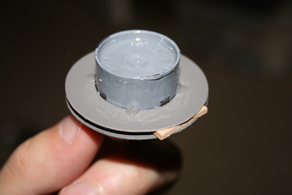
Glue on the fins with a little CA glue. I used a few pieces of balsa to evenly space out the fins.
The tube looks a little grotty, but that's just some glue and missing paint which I cleaned up after I took this pic.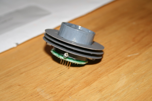
Finished DBU filter.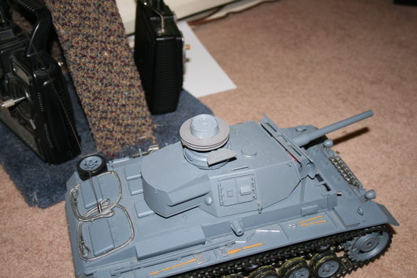
Mounted on PzIII. Not too bad. Maybe I'll build the next one in the shape of a tank commander.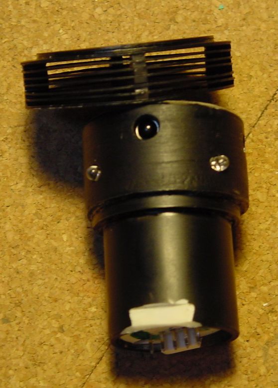
Matt made a much nicer filter, and even placed the DBU on a raised connector. Pity RCG decided to freak out and delete the thread...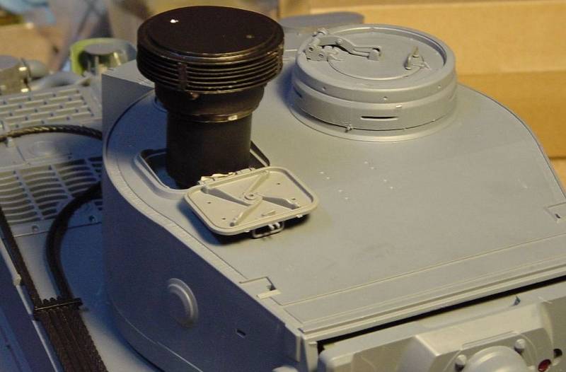
Very nice work Matt!