- Links Page
- Image Gallery
- Resistor Calc
- HomeBuilt IRDA module
- Remote Control IR
- Remote Control DIYUHF
- Remote Control DIYUHF V3
- Remote Control DIYUHF Plantraco compatible
- Battle Circuit for Heng Long Tanks
- DSO Nano review
- Power Meter Monitor
© <in der past>
These are the assembly instructions for version 1.6 DBCs.
They assume the user has a passing familiarity with soldering electronics and identifying components (resistors, capacitors, etc). A 15 watt soldering iron is preferred..
-
Last minute additions not reflected in the pictures below: Version 2.0 DBC PCBs have the unused R4 and R5 removed, and have labelled outputs for the sound power, ground, hit, and fire/dest sounds. Version 1.6 changed the jumper uses. The "Mom" pin became the "block recoil pin" or "REC" and the "SPN" pin is no longer used. The PCB may have aa small label to indicate this change. The jumper block is now only 2x3 pins, and must be installed in the top 3 "rows", leaving the bottom row unused.
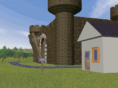
Version 1.6 may also include sockets and pin plugs for both ends of the DBC <-> DBU connection, and the DBC <-> Sound Chip connection. The pin plugs may need to be snapped apart, and I highly recommend that you paint one edge and label the plugs to ensure correct connections are made!!! -
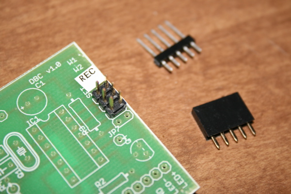
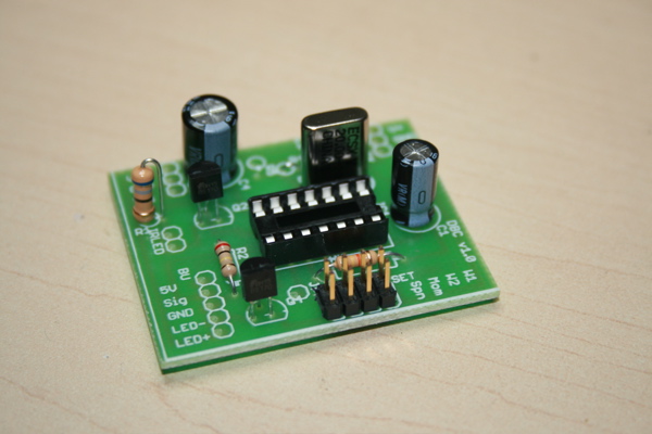
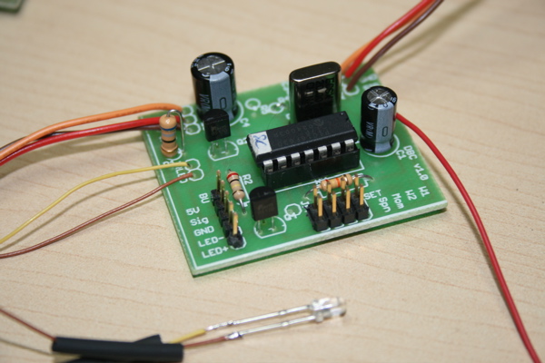
Find the DBC Printed Circuit Board (PCB). The top surface is labelled in white. -
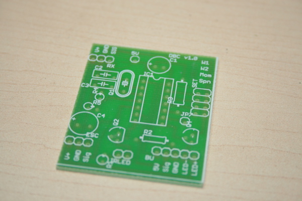
Solder the crystal in at location Q1. Solder the 14 pin DIP socket in at location IC1, aligning the notch with the outline on the board. -
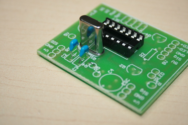
Solder the two 20 pf capacitors in at locations C2 & C3.
Pre-v2 only: Install a jumper at location R4 (use a clipped lead from a capacitor or resistor) -
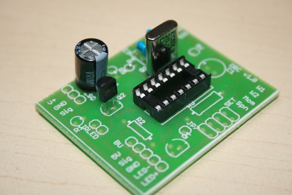
Solder in the 470 uF capacitor at location C4, being careful to match the polarity (the stripe is negative). Solder in one of the two FET transistors at location Q2. -
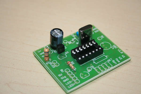
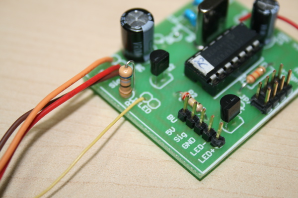
Solder in a 200k ohm resistor (red, black, yellow, gold) at location R2.
- If you're using the LED supplied with the DBU, install a jumper in the location R1. (use a clipped leg from R2)
- If you're using a Tamiya TBU LED or RadioShack LED, install a (not supplied) 68 ohm resistor (blue, grey, black, gold) resistor at R1. You may optionally choose to install the jumper (as above) and install the resistor inline with the LED.
-
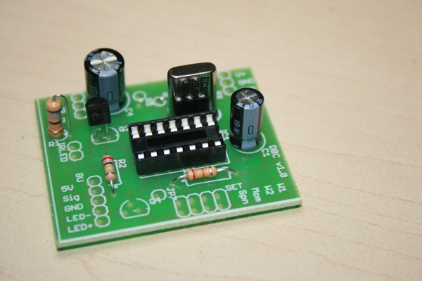
Solder in the 1 uF capacitor at location C1, being careful to match the polarity (the stripe is negative).
(Pic not updated yet) Ignore the resistor location R3
-
Solder in one of the two FET transistors at location Q4.
(Pic not updated yet) Solder in the 2x3 pin jumper block at location "SET", (pre-v2 only: ensuring that the block is in the "topmost" position [see step #1])
-
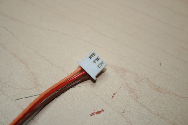
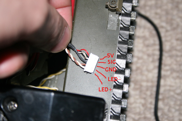
Take one end (doesn't matter which end) of the Heng Long jumper lead that goes between the RX (the smaller board) and the ESC board (the larger board), and hold it as shown so that the metal bottoms of the pins can be seen.
In this picture, the wires are BROWN=SIGNAL, RED=GROUND, ORANGE=BATTERY+. Heng Long is not always consistent with using wire colors, so if your colors are different, you will have to adjust the instructions accordingly.Failure to do so will result in damage to your Heng Long boards and/or the DBU/DBC units. I will use the wire function followed by the color in brackets with a question mark to denote the possibility of a different color.
-
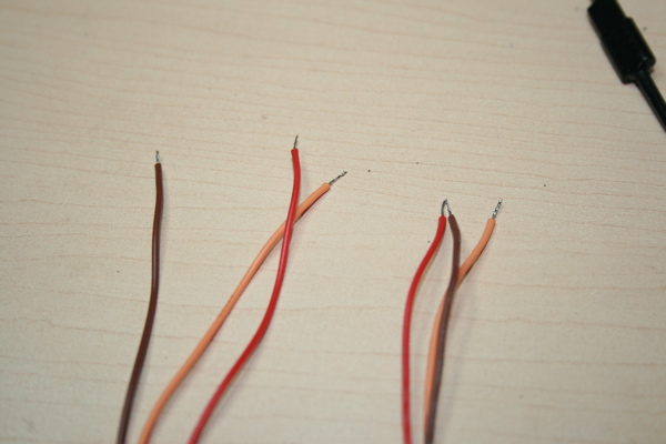
Determine where you will locate the DBC board in your tank. Then cut the Heng Long jumper wire so that both ends will still be able to reach the two Heng Long boards. You may need to splice more wire into the connection if the DBC board needs to be placed far away from the Heng Long boards. Strip and tin the ends of the wires. -
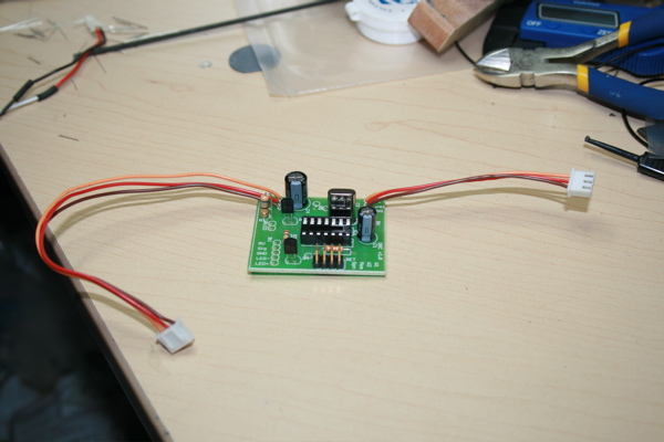
Solder the two ends of the jumper wires to the DBC. The wire to the Heng Long RX goes to location "RX", the wire to the ESC board goes to location "ESC". Ensure that you match up the SIGNAL (brown?) with "SIG", the GROUND (red?) with "GND", and BATTERY+(orange?) with "V+". -
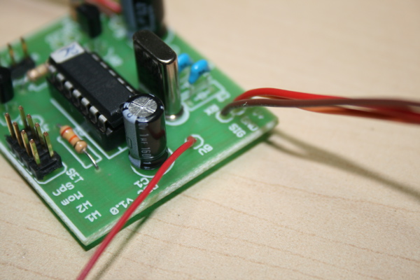
Connect a wire (preferably red) to the location "5V" on the DBC board. Install the "PIC16F630" IC into the socket on the board, ensuring that you match the notch with the notch in the socket and on the board diagram. -
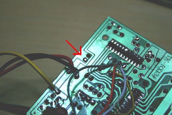
Connect the other end of the "5V" wire to this location on the Heng Long ESC board (you may wish to use some sort of connector for easy removal).
-
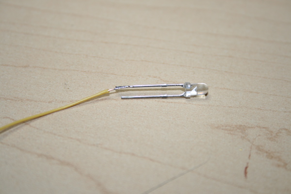
If using a DBU, solder a wire to the long leg of the supplied IR LED. -
Connect that wire to the location "IR LED" in the hole next to the label for "R1". -
Connect a 2nd wire to the short leg of the IR LED and solder to the second pin at location "IR LED". Insulate both leads with heatshrink or tape. - Connect the appropriate signals on the DBC to the matching signals on a DBU (see DBU instructions) or Tamiya TBU (see below). You may wish to use the included connectors for convienence.
-
If connecting the DBC to a Tamiya TBU, use this pinout (you need to either cut the Tamiya connector or find a matching one).- Red = 5v
- White = Sig
- Black = GND
- Brown = LED-
- White = LED+