- Links Page
- Image Gallery
- Resistor Calc
- HomeBuilt IRDA module
- Remote Control IR
- Remote Control DIYUHF
- Remote Control DIYUHF V3
- Remote Control DIYUHF Plantraco compatible
- Battle Circuit for Heng Long Tanks
- DSO Nano review
- Power Meter Monitor
© <in der past>
These are the instructions for adding the 2 clip sound chip to version 1.5+ DBCs.
Recoding tips:
- The sound should be recorded at a pretty high volume, with little background noise.
- Don't expect punchy bass or crisp treble through the HL sound system, instead use sound effects with a high dynamic range
- The hit sound shouldn't be any longer than 2.5-3 seconds, or a second hit will not trigger a 2nd hit sound but will instead shut off the 1st sound (the hit will still count though).
- The death sound shouldn't be any longer than 15 seconds.
- On version 1.6+ DBCs, the "death" sound is used as the "fire" sound when the "block recoil" option is enabled. The "Fire" sound should be as short as possible (1-3 seconds) or a hit sound may be missed (it will still count). Also, when "block recoil" is enabled, the "hit" sound is played for normal hits and the final hit.
- The automatic gain of the chip will ramp up the gain if the sound goes quiet on the end. Then, when you let go of the record button, the noise the button makes will come across as a "donk" sound. Either stop recording before the sound effect completely fades (the cutoff will be masked by the engine noise), or press the effect buttons gently from the "edge" and release gently (this will produce a reduced sound).
- Use a multi-track sound editor (like the free/open-source Audacity) to mix together various sound effects.
Sample sounds:
DBC Hit
DBC Hit type 2
DBC Death starts off like DBC Hit before continuing
-
DBC & DBU with sound chip installed. Tamiya FO Sherman has sound muted. -
DBC & DBU with sound chip installed. Tamiya FO Sherman as opposition.
Installation Instructions:
-
Important for v1.0 upgraders:
If there is a jumper on the "SPN" setting, remove it. I'd recommend carefully cutting or desoldering the "SPN" jumper pins from the block to prevent accidently placing a jumper on them.
(pre v2 only) Remove the resistor at location R3 on the DBC.
-
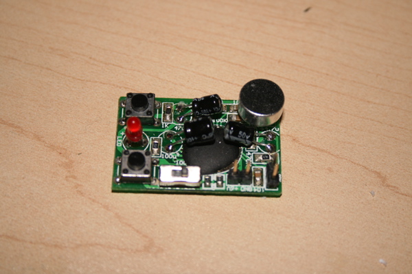
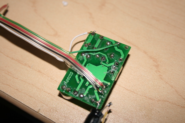
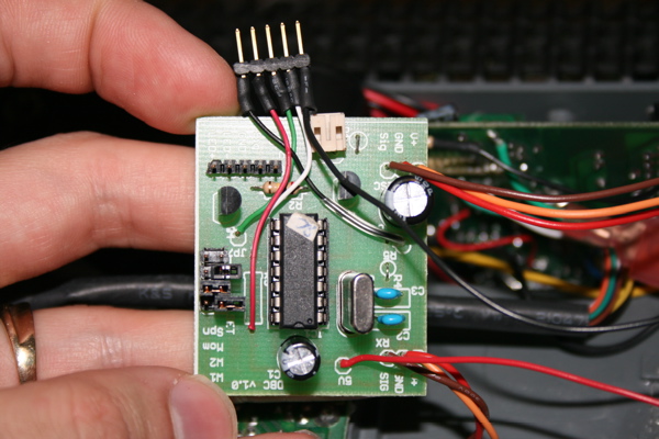
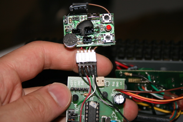
Sound chip. In this picture, the top button is for the "death" (optionally "fire" on v1.6 DBCs) and the bottom button is for the "hit" sound. -
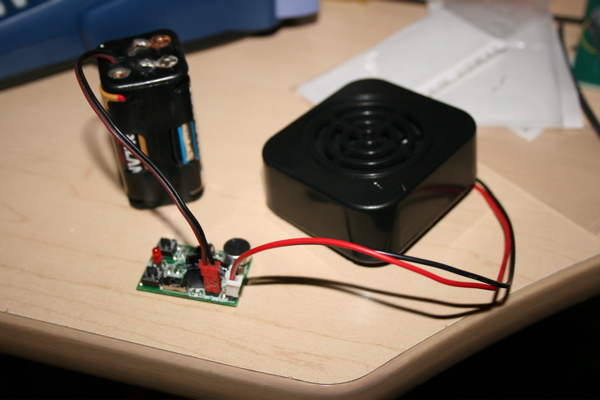
Connect a 5-6V battery (a JST plug fits nicely) using the marked polarity and record the appropriate sounds. The instructions are available here. (basically flip the switch to rec and hold down the appropriate button, release to finish, move switch to play and hit button to demo)
A stock Heng Long speaker fits on the speaker pins, allowing you to judge the quality of your recording. Note that the volume is much lower than the volume available when the sound is amplified by the tank electronics. -
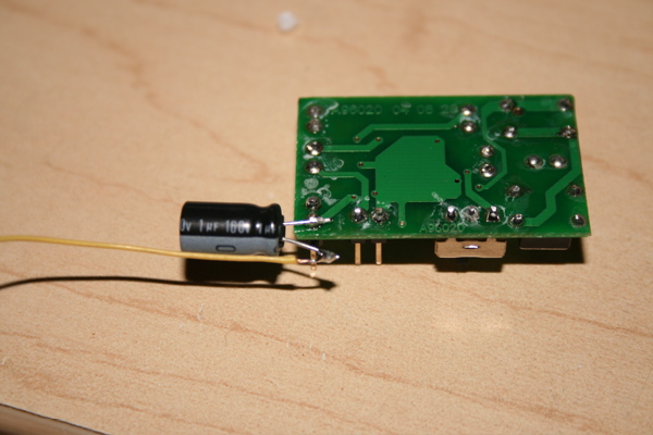
If you're connecting the output to the Heng Long sound system, solder the positive pole of a 1uf or 2.2uf capacitor to either of the two speaker outputs on the underside. Using the underside makes it easier to remove the unit and connect a speaker when recording new sounds. Connect a long wire to the negative side of the capacitor, this wire will need to be long enough to reach the Heng Long ESC board.
If you're using a standalone speaker, connect it directly to the speaker outputs.
Make sure you only connect one type of output
-
Solder a red wire to the underside of the 6v pin, and a black wire to the underside of the ground pin. Solder two wires to these locations under the buttons. Make a note of which wire is connected to which button (see step #2) -
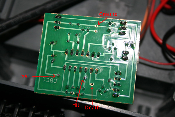
(pre v2 only) Connect the red 6v wire from the sound chip to the location indicated as "5V+" here (one side of where R3 was removed). Solder the black Ground wire to the location indicated as "Ground" here. Solder the "hit" button wire to the location indicated (the other end of where R3 was removed). Solder the "death" button wire to the location "JP7".
(v2+ only) This pic has not been updated yet. Connect the red 6v wire from the sound chip to the location labelled "SND+". Solder the black Ground wire to the location "SNDG". Solder the "hit" button wire to the location labelled "hit". Solder the "death/fire" button wire to the location labelled "dest"". -
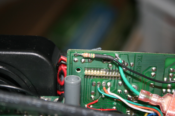
If you wish to connect the sound chip to the Heng Long sound system, connect the wire from the capacitor (see step #4) to this point on the Heng Long board. (note that I switched from a yellow wire in step #4 to a black wire between photos...oops). You may optionally use a 560 ohm resistor (green, blue, brown) as shown to provide a more matched sound, but with less "impact". - Your sound chip is now correctly connected. When hit, the tank will play the "hit" sound. After sufficient hits, it will play the "death" sound. Carefully locate the sound chip where it will not short against either the DBC or any other metal parts (you may want to insulate it with shrink wrap or electrical tape.)
-
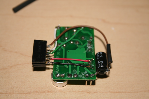
You may want to connect all the wires on the sound chip to a connector (included in v1.6 preordered kits) and then use a mating connector on the other end (included in v1.6 preorderd kits).
Before I started including connectors, I used a floppy drive connnector on the sound chip and a jumper header from an old motherboard on the other end. -
This makes it easier to pull the sound chip off for future recordings.